


 Print
Print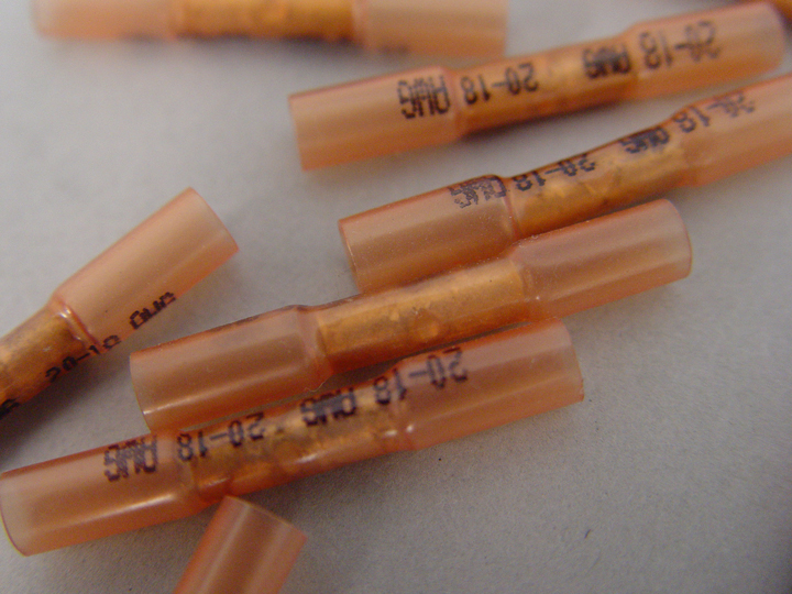 Figure 1 - These crimp and seal splice sleeves have special heat shrink sleeves on each end that shrink around the wire and form an air-tight seal.Confusion exists within the collision industry concerning the repair of some damaged wiring and wiring connectors for restraints systems. The perception is that restraints system wiring should never be repaired. While it is true that some vehicle makers do not recommend the repair of wiring and connectors for the restraints system, others have very detailed printed procedures and even offer repair kits expressly for the repair of restraints system wiring. Repairing damaged restraints system wiring, when applicable and the parts and procedures are available, can save unnecessary replacement of the main body and instrument panel wiring harnesses.
As an example, this article will focus on the repair of restraint system wiring on General Motors (GM) vehicles. Whenever doing restraint system wiring repairs, always follow the procedures and use the parts and equipment specified by the vehicle maker for the vehicle being repaired. This information can be found typically in the “BODY” section of the service information under “WIRING REPAIR” for GM vehicles.
Self Diagnostics
Let’s begin with some background on how the self-diagnostic capabilities of modern restraint systems function. When a problem exists in the electrical circuit of a restraint system, a diagnostic trouble code (DTC) is stored in the restraint system control module and a malfunction indicator lamp (MIL), or airbag warning lamp, on the instrument panel is turned on to alert the driver. The computer is able to detect problems by monitoring system voltage, amperage, and resistance readings, and comparing them to specified values. If a monitored value falls outside the programmed parameters, a DTC is set and the MIL is turned on. Wiring repairs done improperly can increase the resistance in a circuit to the point that the control module senses a fault and sets a DTC. Repairs that do not completely seal the splice joint from moisture can allow corrosion of the connection. This corrosion will also increase circuit resistance and eventually lead to a DTC and MIL.
Restraint System Requirements
What makes a restraint system wiring repair different from any other wiring repair? While there are a couple of recommendations that may be specific to restraint systems, the reality is that restraint system wiring repair demands the same best practices that should be observed with any other wiring repair. The first, and maybe only real difference, is that while GM recommends repairs rather than the replacement of a wiring harness, short pigtails that are attached to parts such as sensors and inflator modules are not repairable. If a pigtail connected to a part is damaged, the part should be replaced.
Restraint system wiring repairs vary from a simple splice of a cleanly cut wire or replacement of sections of damaged wire, to replacement of terminals or even entire connectors. All of these operations may involve splicing wires together.
Splice Sleeves
To help address the issue of making low resistance and moisture-proof, or air-tight splices, special “DuraSeal” crimp and seal splice sleeves were designed (see Figure 1). These connectors differ from the conventional butt connectors in a couple of important ways. First, they have a special cross-hatched (knurled) core crimp barrel that provides the necessary contact integrity to make a low resistance splice. Secondly, they have a special heat shrink sleeve that contains a sealing adhesive inside. When the connectors are heated, they shrink over the wire and make an air-tight seal that protects the connection from the environment. Although these connectors were initially designed for repairing restraint system wiring, because of their superior performance, they are now the recommended splice by GM for all wiring repairs. The only limitation these connectors have is that they can only be used to splice two wires together. For repairs to original equipment splices of three or more wires, special splice clips are available from GM. These types of connections are typically limited to grounds and their application to restraint system wiring is not common. The splice clips have detailed instructions included for applications and usage.
The splice sleeves are available in different sizes and are color coded. Green colored splices (88988379) are used for 22-24 gauge, salmon (#12089189) for 18-20 gauge, blue (12089190) for 14-16 gauge, and yellow (12089191) for 10-12 gauge. To ensure circuit integrity the correct splice sleeve for the wire size must be used.
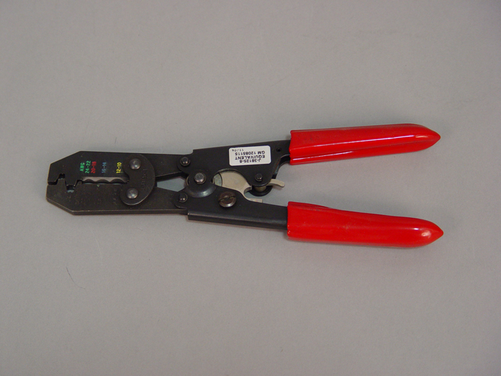 Figure 2 - This special splice-crimping tool is designed to work with the crimp and seal splice sleeves, and ensures that the insulation tubing is not damaged.The tools and procedures used when making wire splices is as important as the type of splice connector. If the crimping tool used on the connector damages the insulation tubing over the metal core crimp barrel, the connection may not be sealed sufficiently from moisture resulting in corrosion. Because of this, GM recommends a special splice crimping tool (J-38125-8, GM P/N 12085115) be used (see Figure 2). The crimping tool has three nest positions. Position 1 is used for 18-24 gauge wire, or the green and salmon colored splice sleeves. Position 2 is for 14-16 gauge wire, or the blue splice sleeves, and position 3 is for 10-12 gauge wire, or the yellow splice sleeves. The nest positions on the crimp tool are color-coded for easy reference (see Figure 3). The crimping tool also has a locking ratchet mechanism in the handle that keeps the tool from being reopened until the proper amount of pressure has been applied to the splice sleeve. After the splice sleeve has been put into the proper nest, and the wire inserted into the metal core crimp, the handles on the crimping tool are closed and squeezed until they open when released. This ensures that just the right amount of pressure is applied to the splice sleeve.
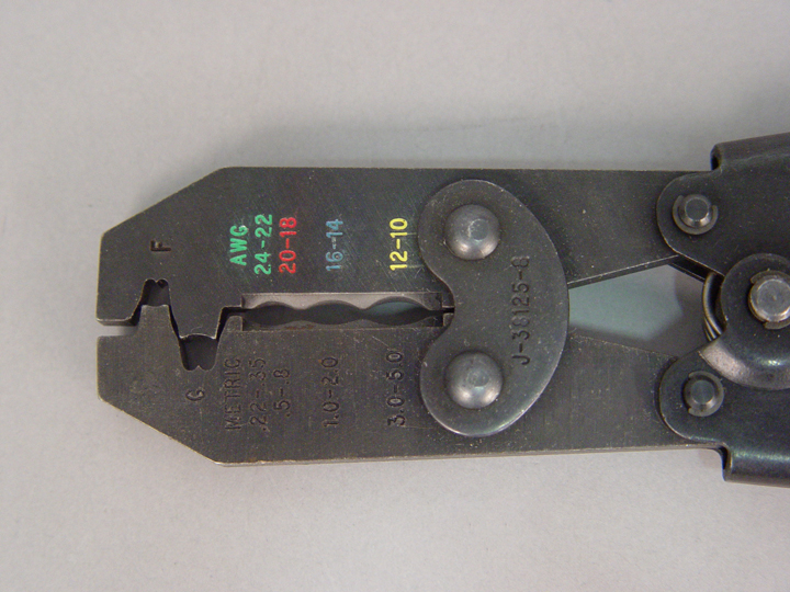 Figure 3 - The splice-crimping tool used to install the crimp and seal splice sleeves has color-coded nest positions to ensure that the correct nest position is used for the application.To repair damage to GM restraint system wiring, follow this procedure in the order listed (see Video).
- Open the wiring harness by removing any tape. Do not damage the wiring insulation when cutting the harness open. A sewing ripper works well for this.
- Cut as little wire off the harness as possible. Damaged sections of wire must be removed and other sections may need to be cut away to change the locations of splices. Splices should be located at least 40 mm (1.5 in) away from harness branches, connectors, or other splices.
- Strip the insulation from the splice locations. You must obtain a clean strip with all of the wire strands intact. If you are unsure of the wire size, and have no way to accurately measure it, begin with the largest opening on the wire stripper and work down until a clean strip of the insulation is achieved. Strip about 7.5 mm (5/16 in) of insulation from each wire to be spliced. After stripping the wire, inspect the wire strands for nicks or cut strands. If any damage is found to the wire, cut the damaged portion off and repeat the stripping procedure.
- Select the proper size splice sleeve for the wire size.
- Obtain the correct splice crimp tool to crimp the splice sleeve.
- Place the splice sleeve in the correct nest of the crimping tool. Ensure that the crimp made falls midway between the end of the metal crimp barrel and the wire stop. The wire stop is in the center of the barrel (see Figure 4). Close the crimping tool handles slightly in order to firmly hold the splice sleeve in the crimp tool nest.
- Insert the wire into the splice sleeve barrel until the wire hits the stop.
- Tightly close the crimping tool handles until they open when released.
- Repeat steps 6-8 for the opposite end of the splice sleeve.
- Using a heat torch (J-38125-5 or equivalent), apply heat to the crimped area of the barrel. Gradually move the heat to the open end of the splice sleeve tubing. The shrink tubing will shrink down tightly against the wire as the heat is applied, and a small amount of sealant will come out of the open end of the tubing. The heat torch used should have a heating barrel to distribute the heat evenly around the entire splice sleeve (see Figure 5).
Video–This video shows the order of repairs to GM restraint system wiring.
Replacing Wiring Harness Parts
Damaged connector terminals present other considerations. The terminals are gold plated to ensure the contact integrity of the sensitive low energy restraint system circuit. Damaged terminals in the sensing and diagnostic module (SDM) harness connector can be replaced, but must only be replaced with the terminated leads in the SIR/SRS connector repair assembly pack. Do not substitute any other terminals for those in the SIR/SRS assembly packs. These terminals are crimped onto short sections of wire that can be spliced into the harness with the splice sleeves after they are inserted into the connector body. Damaged terminals in other restraint system connectors are repaired by splicing a new connector assembly into the wiring harness. The wiring harness side connectors are available as service parts.
When sections of wire require replacement, ensure that the wire used is the same wire size and type as that being replaced. Other parts that are available for restraint system wiring repairs include connector position assurance (CPA) inserts and terminal position assurance (TPA) inserts (see Figure 6). The CPAs are inserted through locking tabs on the connectors to ensure that the connector halves cannot vibrate apart, and the TPAs keep the terminal pins seated securely in the connector body. Both of these inserts must be undamaged and in place to ensure good contact between the mating terminals of the connection.
All of these parts are available separately or in an SIR Repair Kit tray. The SIR tray is a part of a bigger Terminal Repair Kit (J-38125) that includes all the tools, connectors, splice sleeves, and other parts to repair any part of a damaged wiring harness. Also included in the SIR Repair Kit tray is shrink tubing that is used to cover splices and protect them from heat in areas where they are exposed to high temperatures. Yellow electrical tape is supplied so that color coding of the wiring can be maintained for splices made in areas that have color-coded wiring.
Conclusion
Restraint system wiring repairs are allowed by several vehicle makers, including GM. While not difficult, always follow the vehicle maker’s recommendations as to the parts and procedures used. This will ensure that the integrity of the system is maintained and that repairs will have the durability necessary to maintain proper system functioning.
This article first appeared in the October 31, 2005 edition of the I-CAR Advantage Online.
Additional I-CAR Collision Repair News you may find helpful: